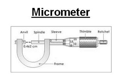
A micrometer, sometimes known as a micrometer screw gauge, is a device incorporating a calibrated screw used widely for precise measurement of small distances in mechanical engineering and machining as well as most mechanical trades, along with other metrological instruments such as dial, vernier, and digital calipers. Micrometers are usually, but not always, in the form of calipers (opposing ends joined by a frame), which is why micrometer caliper is another common name. The spindle is a very accurately machined screw. The object to be measured is placed between the spindle and the anvil. The spindle is moved inward by turning the ratchet knob or thimble until the object to be measured is lightly touched by both the spindle and the anvil. The sleeve through which the spindle moves is graduated with marks 0.025 inch (0.635 mm) apart, with the number 1 on the sleeve representing 0.1 inch (2.54 mm), 2 representing 0.2 inch complete turn for each 0.025 inch on the sleeve scale, and the thimble scale is graduated from 0 to 25. Thus use of the two scales permits a reading to the nearest 0.001 inch (0.025 mm).
Types
Basic types · Outside micrometer (aka micrometer caliper), typically used to measure wires, spheres, shafts and blocks.
· Inside micrometer, used to measure the diameter of holes.
· Depth micrometer, measures depths of slots and steps.
Specialized types Each type of micrometer caliper can be fitted with specialized anvils and spindle tips for particular measuring tasks. For example, the anvil may be shaped in the form of a segment of screw thread, in the form of a v-block, or in the form of a large disc.
· Universal micrometer sets come with interchangeable anvils, such as flat, spherical, spline, disk, blade, point, and knife-edge. The term universal micrometer may also refer to a type of micrometer whose frame has modular components, allowing one micrometer to function as outside mic, depth mic, step mic, etc. (often known by the brand names Mul-T-Anvil and Uni-Mike).
· Blade micrometers have a matching set of narrow tips (blades). They allow, for example, the measuring of a narrow o-ring groove.
· Pitch-diameter micrometers (aka thread mics) have a matching set of thread-shaped tips for measuring the pitch diameter of screw threads.
· Limit mics have two anvils and two spindles, and are used like a snap gauge. The part being checked must pass through the first gap and must stop at the second gap in order to be within specification. The two gaps accurately reflect the top and bottom of the tolerance range.
· Bore micrometer, typically a three-anvil head on a micrometer base used to accurately measure inside diameters.
· Tube micrometers have a cylindrical anvil positioned perpendicularly to a spindle and is used to measure the thickness of tubes.
· Micrometer stops are micrometer heads that are mounted on the table of a manual milling machine, bedways of a lathe, or other machine tool, in place of simple stops. They help the operator to position the table or carriage precisely. Stops can also be used to actuate kickout mechanisms or limit switches to halt an automatic feed system.
· Ball micrometers have ball-shaped (spherical) anvils. They may have one flat and one ball anvil, in which case they are used for measuring tube wall thickness, distance of a hole to an edge, and other distances where one anvil must be placed against a rounded surface. They differ in application from tube micrometers in that they may be used to measure against rounded surfaces which are not tubes, but the ball anvil may also not be able to fit into smaller tubes as easily as a tube micrometer. Ball micrometers with a pair of balls can be used when single-tangential-point contact is desired on both sides. The most common example is in measuring the pitch diameter of screw threads (which is also done with conical anvils or the 3-wire method, the latter of which uses similar geometry as the pair-of-balls approach).
· Bench micrometers are tools for inspection use whose accuracy and precision are around half a micrometer (20 millionths of an inch, "a fifth of a tenth" in machinist jargon) and whose repeatability is around a quarter micrometer ("a tenth of a tenth"). An example is the Pratt & Whitney Super micrometer brand.
· Digit mics are the type with mechanical digits that roll over.
· Digital mics are the type that uses an encoder to detect the distance and displays the result on a digital screen.
· V mics are outside mics with a small V-block for an anvil. They are useful for measuring the diameter of a circle from three points evenly spaced around it (versus the two points of a standard outside micrometer). An example of when this is necessary is measuring the diameter of 3-flute end mills and twist drills.
Micrometers use the principle of a screw to amplify small distances (that are too small to measure directly) into large rotations of the screw that are big enough to read from a scale. The accuracy of a micrometer derives from the accuracy of the thread-forms that are at its heart. In some cases it is a differential screw. The basic operating principles of a micrometer are as follows:
1.. The amount of rotation of an accurately made screw can be directly and precisely correlated to a certain amount of axial movement (and vice versa), through the constant known as the screw's lead A screw's lead is the distance it moves forward axially with one complete turn (360°). (In most threads [that is, in all single-start threads], lead and pitch refer to essentially the same concept.)
2.. With an appropriate lead and major diameter of the screw, a given amount of axial movement will be amplified in the resulting circumferential movement.
For example, if the lead of a screw is 1 mm, but the major diameter (here, outer diameter) is 10 mm, then the circumference of the screw is 10π, or about 31.4 mm. Therefore, an axial movement of 1 mm is amplified (magnified) to a circumferential movement of 31.4 mm. This amplification allows a small difference in the sizes of two similar measured objects to correlate to a larger difference in the position of a micrometer's thimble. In some micrometers, even greater accuracy is obtained by using a differential screw adjuster to move the thimble in much smaller increments than a single thread would allow.
In classic-style analog micrometers, the position of the thimble is read directly from scale markings on the thimble and shaft. A vernier scale is often included, which allows the position to be read to a fraction of the smallest scale mark. In digital micrometers, an electronic readout displays the length digitally on an LCD display on the instrument. There also exist mechanical-digit versions, like the style of car odometers where the numbers "roll over".
Reading Inch system
The spindle of an inch-system micrometer has 40 threads per inch, so that one turn moves the spindle axially 0.025 inch (1 ÷ 40 = 0.025), equal to the distance between two graduations on the frame. The 25 graduations on the thimble allow the 0.025 inch to be further divided, so that turning the thimble through one division moves the spindle axially 0.001 inch (0.025 ÷ 25 = 0.001). Thus, the reading is given by the number of whole divisions that are visible on the scale of the frame, multiplied by 25 (the number of thousandths of an inch that each division represents), plus the number of that division on the thimble which coincides with the axial zero line on the frame. The result will be the diameter expressed in thousandths of an inch. As the numbers 1, 2, 3, etc., appear below every fourth sub-division on the frame, indicating hundreds of thousandths, the reading can easily be taken mentally. Suppose the thimble were screwed out so that graduation 2, and three additional sub-divisions, were visible (as shown in the image), and that graduation 1 on the thimble coincided with the axial line on the frame. The reading then would be 0.2000 + 0.075 + 0.001, or .276 inch.
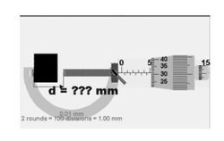
Metric system The spindle of an ordinary metric micrometer has 2 threads per millimetre, and thus one complete revolution moves the spindle through a distance of 0.5 millimeter. The longitudinal line on the frame is graduated with 1 millimetre divisions and 0.5 millimetre subdivisions. The thimble has 50 graduations, each being 0.01 millimetre (one-hundredth of a millimetre). Thus, the reading is given by the number of millimetre divisions visible on the scale of the sleeve plus the particular division on the thimble which coincides with the axial line on the sleeve.
Suppose that the thimble were screwed out so that graduation 5, and one additional 0.5 subdivision were visible (as shown in the image), and that graduation 28 on the thimble coincided with the axial line on the sleeve. The reading then would be 5.00 + 0.5 + 0.28 = 5.78 mm.
1.. The amount of rotation of an accurately made screw can be directly and precisely correlated to a certain amount of axial movement (and vice versa), through the constant known as the screw's lead A screw's lead is the distance it moves forward axially with one complete turn (360°). (In most threads [that is, in all single-start threads], lead and pitch refer to essentially the same concept.)
2.. With an appropriate lead and major diameter of the screw, a given amount of axial movement will be amplified in the resulting circumferential movement.
For example, if the lead of a screw is 1 mm, but the major diameter (here, outer diameter) is 10 mm, then the circumference of the screw is 10π, or about 31.4 mm. Therefore, an axial movement of 1 mm is amplified (magnified) to a circumferential movement of 31.4 mm. This amplification allows a small difference in the sizes of two similar measured objects to correlate to a larger difference in the position of a micrometer's thimble. In some micrometers, even greater accuracy is obtained by using a differential screw adjuster to move the thimble in much smaller increments than a single thread would allow.
In classic-style analog micrometers, the position of the thimble is read directly from scale markings on the thimble and shaft. A vernier scale is often included, which allows the position to be read to a fraction of the smallest scale mark. In digital micrometers, an electronic readout displays the length digitally on an LCD display on the instrument. There also exist mechanical-digit versions, like the style of car odometers where the numbers "roll over".
Reading Inch system
The spindle of an inch-system micrometer has 40 threads per inch, so that one turn moves the spindle axially 0.025 inch (1 ÷ 40 = 0.025), equal to the distance between two graduations on the frame. The 25 graduations on the thimble allow the 0.025 inch to be further divided, so that turning the thimble through one division moves the spindle axially 0.001 inch (0.025 ÷ 25 = 0.001). Thus, the reading is given by the number of whole divisions that are visible on the scale of the frame, multiplied by 25 (the number of thousandths of an inch that each division represents), plus the number of that division on the thimble which coincides with the axial zero line on the frame. The result will be the diameter expressed in thousandths of an inch. As the numbers 1, 2, 3, etc., appear below every fourth sub-division on the frame, indicating hundreds of thousandths, the reading can easily be taken mentally. Suppose the thimble were screwed out so that graduation 2, and three additional sub-divisions, were visible (as shown in the image), and that graduation 1 on the thimble coincided with the axial line on the frame. The reading then would be 0.2000 + 0.075 + 0.001, or .276 inch.
Metric system The spindle of an ordinary metric micrometer has 2 threads per millimetre, and thus one complete revolution moves the spindle through a distance of 0.5 millimeter. The longitudinal line on the frame is graduated with 1 millimetre divisions and 0.5 millimetre subdivisions. The thimble has 50 graduations, each being 0.01 millimetre (one-hundredth of a millimetre). Thus, the reading is given by the number of millimetre divisions visible on the scale of the sleeve plus the particular division on the thimble which coincides with the axial line on the sleeve.
Suppose that the thimble were screwed out so that graduation 5, and one additional 0.5 subdivision were visible (as shown in the image), and that graduation 28 on the thimble coincided with the axial line on the sleeve. The reading then would be 5.00 + 0.5 + 0.28 = 5.78 mm.
 RSS Feed